NOR Gate
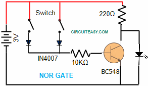
NOR Gate is combination of OR Gate whose output is followed by a NOT Gate. Below is the picture of our experiment conducted.


Circuit Diagram of NOR Gate
Parts List:
Two Switches
One LED
Transistor BC548
Diode 2 Pcs IN 4007
Resistance 220 Ohms, 10K ohms
Battery container for 2 cell.
In this project OR gate is constructed using two Diodes. Input level for each diode is fed by two individual switches.
Here NOT Gate circuit is made using a NPN transistor such that when there is no current flow(+ve voltage) to Base then NPN transistor will not conduct and in that case we will get some positive voltage from resistance R1. But as soon as current flows through Base of Transistor it becomes conductor and it drops voltage received by Resistance R1 since current flows from collector to emitter in NPN transistor(common emitter circuit) and output becomes zero.Output of OR gate is fed to NOT gate through a resistance R2 (10K Ohms )and output of NOT gate is fed to a LED for logic level indication.